


What Is a PD Charger and Why It Matters for Fast Charging
 06 Feb,2026
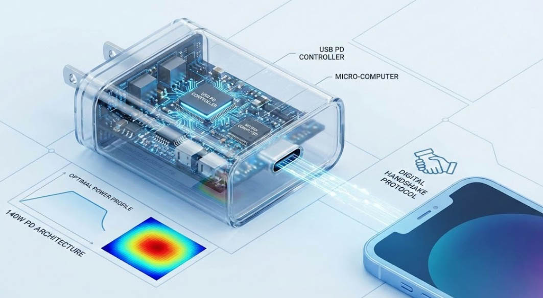
For B2B electronics buyers and sourcing managers, understanding the architecture of a usb phone charger is no longer just about checking voltage and amperage ratings. The transition from legacy charging to USB Power Delivery (PD) represents a fundamental shift in how power is negotiated and delivered. As an engineer who has overseen the transition from basic 5W adapters to high-density 140W PD architectures, I have seen firsthand how critical the handshake protocol is between the source and the sink (the device).
The modern usb phone charger equipped with PD technology is essentially a micro-computer. It communicates directly with the connected device to determine the optimal power profile, a feature absent in older standards. For distributors, selecting the right charger involves analyzing efficiency curves and thermal behaviors rather than just marketing specifications.
Technical Fundamentals of the Modern USB Phone Charger
At the core of a PD-enabled usb phone charger is the controller IC, which manages the communication channel (CC) lines in the USB-C connector. Unlike legacy chargers that relied on D+/D- voltage dividers to signal current capability, PD chargers utilize a digital packet-based communication system.
Key technical components include:
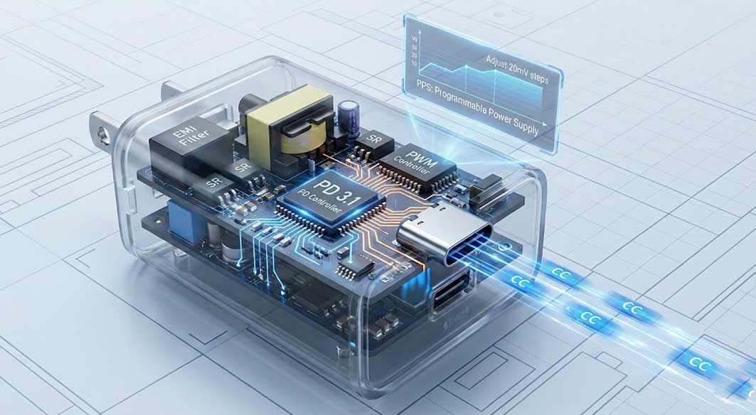
PD Controller: Handles the protocol negotiation (e.g., offering 5V, 9V, 15V, 20V profiles).
PWM Controller: Adjusts the duty cycle of the primary switch to regulate output voltage based on the PD controller's feedback.
Synchronous Rectification (SR): Replaces output diodes with MOSFETs to significantly reduce conduction losses and improve efficiency.
EMI Filter: Essential for suppressing conductive and radiated noise, ensuring the charger does not interfere with wireless signals.
This architecture supports features like Programmable Power Supply (PPS), allowing the phone to request voltage adjustments in 20mV steps. This granular control reduces conversion loss inside the phone, thereby lowering the device's temperature during fast charging.
Industry Pain Points in Mass Production
When sourcing a usb phone charger at scale, reliability issues often stem from aggressive cost-cutting in invisible areas. High return rates in the consumer electronics market are frequently traced back to poor Thermal Management strategies.
Common failure modes observed in the lab include:
Capacitor Derating Failure: Using output capacitors with insufficient voltage margins leads to premature electrolyte drying and eventual short circuits.
Thermal Throttling: Chargers that lack adequate heat dissipation structures (like potting or heatsinks) will rapidly drop power output to protect components, failing to deliver the advertised charging speed.
Connector Stress: The mechanical fatigue of the USB-C port is a leading cause of field failure, often ignored during the design phase.
Engineering Trade-off Analysis: Density vs. Reliability
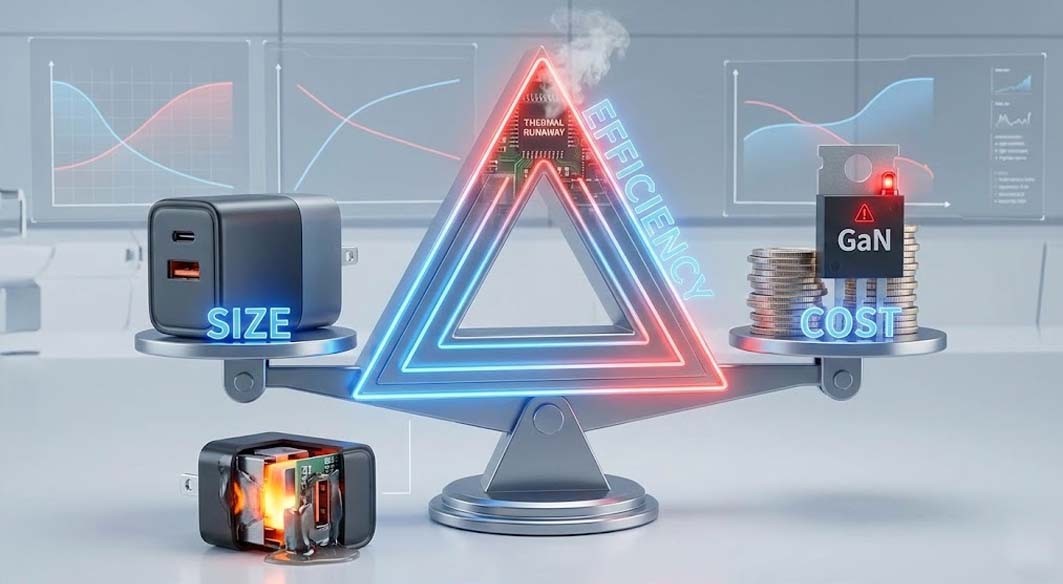
In power supply design, there is an immutable "Iron Triangle": Size, Efficiency, and Cost. You can optimize two, but rarely all three. A critical trade-off often misunderstood by buyers is the push for "ultra-miniature" sizes.
To make a usb phone charger extremely small, engineers must increase the Switching Frequency Optimization. While higher frequency allows for smaller transformers and capacitors, it dramatically increases switching losses (heat). To counter this, expensive active clamp topologies or GaN switches are required.
However, in many "budget" compact chargers, manufacturers skip the necessary thermal mitigation. They pack components tightly without potting compounds to save weight and cost. The result is a charger that gets dangerously hot, degrades its internal plastic insulation, and creates a safety hazard over time. From an engineering standpoint, accepting a slightly larger form factor often yields a product with significantly better thermal headroom and a longer MTBF (Mean Time Between Failures).
Engineering Solution Methodology: Design Philosophy in Practice
In one internal engineering reference case (Tommox), specific engineering choices focus on the longevity of the control loop rather than peak specification marketing. For instance, in 65W and 100W reference designs, the implementation of Ripple Control techniques is prioritized over absolute minimum casing size.
The engineering approach includes:
Full Potting Injection: Tommox designs often utilize high-conductivity potting glue. While this adds weight and manufacturing cost, it creates a uniform thermal mass, preventing hot spots on the primary MOSFETs.
Safety Margin Protocol: Components are selected with a voltage rating buffer of at least 20% above peak operating conditions to handle transient spikes from unstable grids.
EMI Optimization: Instead of minimal filtering to barely pass certification, multi-stage filtering is used to ensure clean power delivery that protects the end-user's sensitive touch screens from "ghost touch" issues caused by noise.
Why GaN Chargers Are Replacing the Traditional USB Phone Charger
The emergence of gan chargers (Gallium Nitride) has revolutionized the specific power density of adapters. Unlike silicon, GaN carries a wider bandgap, allowing for faster switching speeds and lower on-resistance
For B2B buyers, switching to gan chargers offers distinct logistical advantages:
Efficiency Gains: GaN systems can achieve efficiency ratings exceeding 93%, reducing energy waste.
Form Factor: A reduction in PCBA size by 40-50% translates to lower shipping volume and warehousing costs.
Thermal Performance: With GaNFast power ICs, the charger generates less heat for the same power output compared to silicon counterparts.
However, the design complexity of GaN requires rigorous Failure Mode Analysis. The high $dv/dt$ (rate of voltage change) in GaN circuits can cause significant electromagnetic interference if the PCB layout is not optimized with minimized loop inductance.
FAQ: Sourcing the Right Charger
Q: Does a higher wattage rating always mean faster charging for all phones?
A: No. The charging speed is dictated by the "handshake." If a phone only supports 20W PD, a 100W usb phone charger will only deliver 20W. However, higher wattage chargers offer "future-proofing" for laptops and tablets.
Q: How do I verify if a supplier uses genuine GaN components?
A: Ask for the BOM (Bill of Materials) or a teardown report. Genuine gan chargers will utilize controllers from reputable brands like Navitas or Innoscience, and the transformer size will be visibly smaller than equivalent silicon chargers.
Q: What is the significance of UL/ETL certification for B2B imports?
A: It is non-negotiable for liability. Non-certified chargers often lack the necessary creepage and clearance distances on the PCB, posing shock risks.
Future Trends & Design Direction
The future of the usb phone charger lies in the evolution of the PD 3.1 standard and UFCS (Universal Fast Charging Specification). We are moving toward Extended Power Range (EPR) capable of delivering up to 240W (48V/5A) via USB-C.
Design trends to watch:
Hybrid Topologies: Combining Totem-Pole PFC with LLC resonant converters for efficiencies approaching 96%.
Intelligent Load Balancing: Multi-port chargers that dynamically reallocate power based on real-time device demand rather than fixed ratios.
Sustainable Materials: The use of PCR (Post-Consumer Recycled) plastics in charger housings to meet EU environmental regulations.
For procurement professionals, the focus must shift from "cost per watt" to "efficiency per cubic inch" and long-term reliability metrics.
 30W vs 45W vs 65W Chargers: Which One Should You Choose?