


What B2B Buyers Should Know Before Ordering Phone Chargers?
 06 Feb,2026
In the consumer electronics supply chain, the retractable cable charger represents one of the most mechanically complex accessories to manufacture reliably. Unlike standard wall adapters, which are purely static electrical devices, retractable units introduce moving parts, variable inductance based on cable extension, and significant thermal constraints. For a sourcing manager or product engineer, evaluating these devices requires looking beyond the wattage rating on the casing.
A high-performance retractable cable charger is not simply a power supply with a cord; it is a convergence of mechanical engineering and power electronics. The failure modes are distinct: spring fatigue, slip-ring connectivity loss, and thermal throttling due to restricted airflow around the internal reel. This guide details the engineering realities necessary for making data-driven procurement decisions.
Technical Fundamentals of Retractable Mechanisms
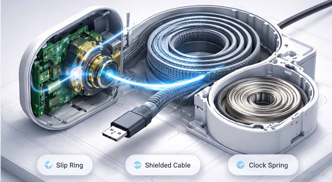
To understand reliability, we must first dissect the anatomy of the device. The core difference between a standard adapter and a retractable wall charger lies in the signal and power transmission path.
The Slip Ring Assembly: Power must be transferred from the stationary PCB to the rotating cable reel. This is typically achieved via a slip ring or a direct-solder spiral method. Poorly designed contact points create high resistance, leading to arcing and voltage instability.
Variable Inductance: When a cable is coiled, it acts as an inductor. While negligible at 5V, at higher power delivery (PD) levels, a tightly coiled cable can generate heat and slightly alter impedance. High-quality designs utilize shielded cabling to mitigate electromagnetic interference (EMI).
Spring Tension Mechanics: The retraction relies on a constant-force spring (clock spring). The metallurgical composition of this spring determines whether the unit lasts for 500 cycles or 5,000 cycles before losing tension or jamming.
Industry Pain Points: Where Generic Designs Fail
When analyzing RMA (Return Merchandise Authorization) data for charging accessories, retractable cable charger units often show specific failure patterns that differ from static chargers.
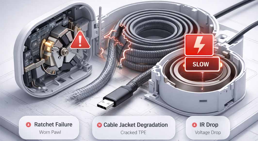
The "Ratchet" Failure: The locking mechanism usually relies on a small plastic or metal pawl. In cost-reduced versions, this pawl wears down, causing the cable to refuse to lock at the desired length or fail to retract completely.
Cable Jacket Degradation: The cable is subjected to friction every time it is pulled. Standard TPE jackets may peel or crack after repetitive friction against the housing aperture.
IR Drop (Voltage Drop): Because retractable cables are often thinner (to fit on the reel) and longer, the resistance is higher. Without voltage drop compensation (Cable Drop Compensation - CDC) in the controller IC, the device at the end of the cable may not receive the full required voltage, leading to slow charging negotiation.
Engineering Trade-off Analysis: Volume vs. Thermals
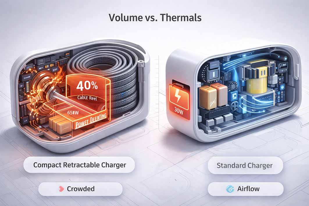
This is the most critical section for decision-makers. In power electronics, there is no "perfect" product; there are only calculated compromises. A retractable cable charger faces a severe volume constraint: the cable reel takes up 30-40% of the internal housing volume, leaving significantly less space for the actual power supply circuitry (PCBA) compared to a standard charger.
The Trade-off: To maintain a compact form factor while housing the mechanism, engineers must increase the switching frequency to shrink the transformer size. However, higher switching frequency generates more switching loss (heat). Since the internal volume is crowded by the plastic reel, airflow is nonexistent, and potting (filling with heat-conductive glue) is difficult without interfering with the moving parts.
The Consequence: If a supplier promises an ultra-miniature retractable wall charger with high wattage (e.g., 65W+) and no active cooling or advanced GaN (Gallium Nitride) topology, the device will likely suffer from aggressive thermal throttling. It may output 65W for two minutes, then drop to 30W to prevent overheating. Buyers must request "Power Derating Curves" rather than just accepting peak wattage claims. Reliable engineering prioritizes sustained performance over impossible size reduction.
Internal Design Philosophy and Structural Implementation
In specific engineering case studies, such as the development cycles observed at Tommox, the conflict between mechanical durability and electrical performance requires distinct architectural choices. When addressing the issue of cable connection fatigue—a common failure point where the cable meets the reel—the engineering team implemented a strain-relief buffer zone rather than a direct rigid connection. This design choice, while increasing the manufacturing assembly time by approximately 15%, significantly reduced the mechanical stress on the solder joints during rapid retraction events. This example illustrates that long-term reliability in moving mechanisms is often achieved by sacrificing assembly speed for structural integrity.
Specification & Approach Comparison
When evaluating supplier proposals for a retractable cable charger, use the following comparison matrix to filter out sub-par designs.
Cable Wire Gauge (AWG):
Standard Market: 24/28 AWG (Higher resistance, voltage drop risks).
Professional Grade: 20/22 AWG for power lines (Minimizes heat generation and IR drop).
Retraction Lifecycle:
Standard Market: Tested to 1,000 – 2,000 cycles.
Professional Grade: Tested to 5,000+ cycles with <5% loss in spring tension.
Housing Material:
Standard Market: ABS (prone to melting/deformation under high heat).
Professional Grade: PC + V0 Flame Retardant materials (High heat resistance and structural rigidity).
EMI Shielding:
Standard Market: Minimal shielding, potential interference with touch screens.
Professional Grade: Full copper foil shielding around the PCBA and grounded cable shielding.
FAQ: Questions for Sourcing Managers
Q: How does the coiled cable affect Data Transfer speeds?
A: A high-quality retractable cable charger that supports data will typically adhere to USB 2.0 or USB 3.0 standards. However, the signal integrity can degrade in poor-quality slip rings. Ensure the factory performs "Eye Diagram" testing to verify signal quality during data transmission.
Q: Can we customize the cable length?
A: Yes, but there is a hard limit based on the housing volume. Extending the cable requires a larger reel and a stronger spring, which exponentially increases the overall size of the retractable wall charger. The standard balance is usually between 80cm and 120cm.
Q: What certifications are mandatory for these mechanical-electrical hybrids?
A: Beyond standard electrical safety (UL/ETL, CE-LVD, FCC), you should look for mechanical stress test reports. There is no specific "retractable" certification, so internal lab reports regarding "Flexing Tests" and "Retraction Durability" are vital.
Future Trends: GaN and Integration
The future of the retractable cable charger lies in the integration of Gallium Nitride (GaN) technology. GaN allows for higher efficiency (93%+) and smaller transformer components. This frees up the crucial internal volume needed for the mechanical reel, allowing for:
Higher Power Density: 100W+ retractable units becoming viable without excessive overheating.
Flat-Reel Designs: Moving away from cylindrical reels to flatter, oval track designs to create slimmer profiles for travel.
Smart Tensioning: Electronic braking systems to replace mechanical pawls, reducing wear and tear.
For buyers, the next step is to request a detailed [custom OEM power solution proposal] that specifically addresses thermal management in restricted-volume housings.
 Why Many 65W GaN Chargers Cannot Sustain Full Power Output