


Everything You Need to Know About Modern Phone Chargers
 06 Feb,2026
In the rapidly evolving landscape of power electronics, the wall charger has transitioned from a simple commodity to a sophisticated power conversion system. For distributors and enterprise buyers, understanding the underlying engineering architecture is no longer optional; it is a prerequisite for minimizing RMA (Return Merchandise Authorization) rates and ensuring long-term reliability.
A modern charger is not merely a transformer; it is a complex assembly of high-frequency switching circuits, protocol controllers, and thermal management systems. As devices demand higher wattage in smaller form factors, the engineering challenges shift from basic voltage regulation to maximizing power density without compromising safety. This article explores the technical nuances, engineering trade-offs, and design philosophies that define high-quality charging solutions in the current B2B market.
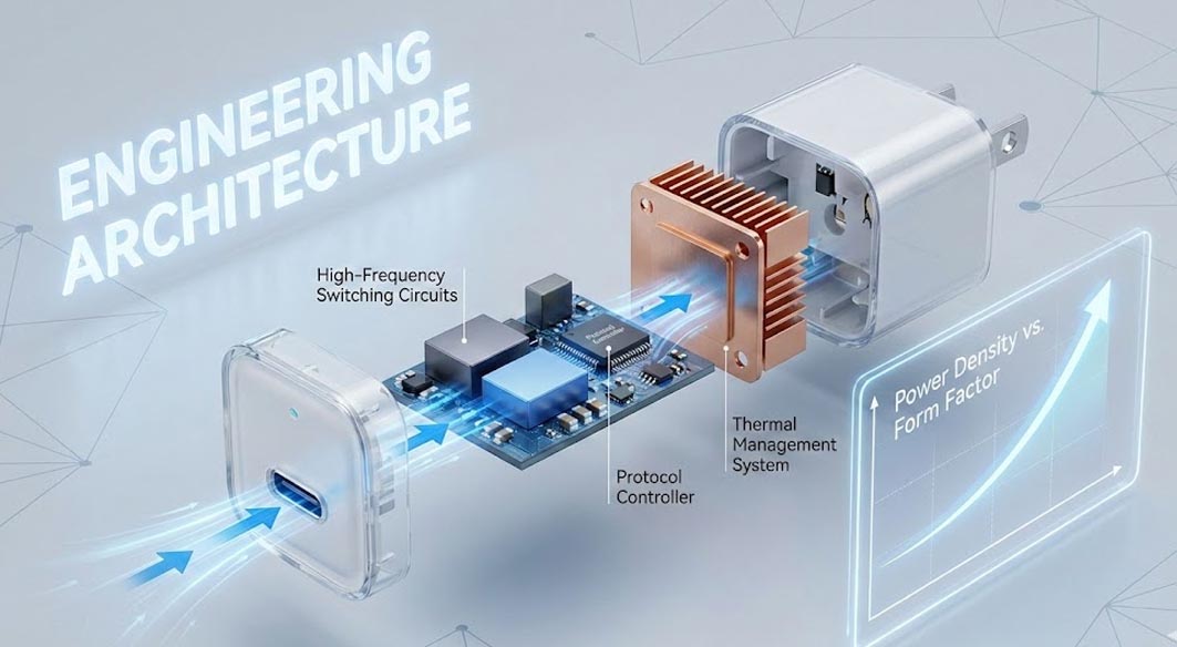
Technical Fundamentals of a Type C Wall Charger
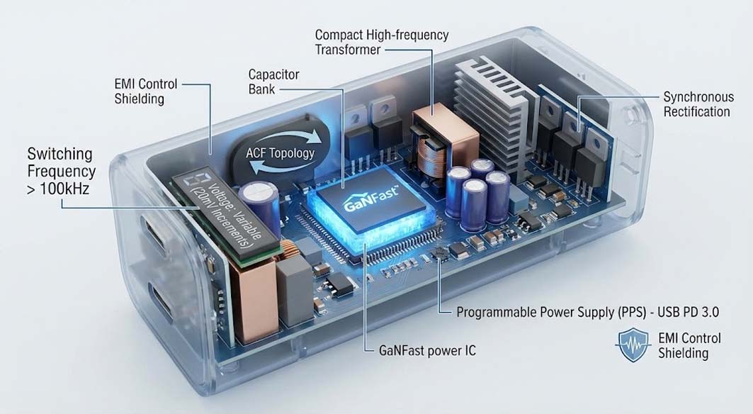
At the heart of every high-performance charger lies the balance between Switching Frequency Optimization and electromagnetic interference (EMI) control. Traditional silicon-based chargers operated at lower frequencies, requiring larger magnetic components.
The introduction of Gallium Nitride (GaN) technology—often utilizing GaNFast power ICs—has allowed engineers to push switching frequencies beyond 100kHz. This reduction in the cycle time allows for significantly smaller transformers and capacitors. However, this creates a new set of challenges regarding signal integrity and heat dissipation.
Key technical components include:
Active Clamp Flyback (ACF) Topology: Used in higher efficiency designs to recycle leakage energy, reducing switching losses compared to standard Quasi-Resonant (QR) flyback architectures.
Programmable Power Supply (PPS): A feature of the USB PD 3.0/3.1 standard that allows the type c wall charger to adjust voltage in 20mV increments. This reduces conversion loss at the phone’s internal charge pump, thereby lowering the device temperature.
Synchronous Rectification: Replacing output diodes with MOSFETs to drastically reduce conduction losses on the secondary side, essential for maintaining high Efficiency.
Industry Pain Points in Mass Production
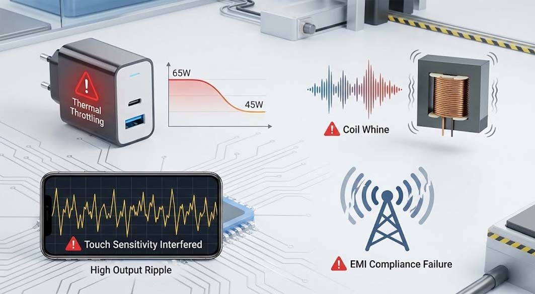
When sourcing a portable usb charger for mass distribution, buyers often encounter specifications that look perfect on paper but fail in real-world scenarios. The disconnect usually stems from testing conditions versus actual usage environments.
Common failure modes and pain points include:
Thermal Throttling: Many compact chargers cannot sustain their rated power (e.g., 65W) for more than 20 minutes before the internal temperature triggers protection mechanisms, dropping the output to 45W or lower.
Audible Noise (Coil Whine): Caused by the magnetostriction of the transformer core or the vibration of ceramic capacitors at light loads. This is often a sign of poor loop compensation or unvarnished transformers.
High Output Ripple: Excessive Ripple Control issues can interfere with the touch sensitivity of the connected device and accelerate battery degradation.
EMI Compliance Failures: Aggressive miniaturization often leads to compromised EMI filter stages, causing the charger to emit noise that interferes with wireless signals.
Engineering Trade-off Analysis: Density vs. Thermal Management
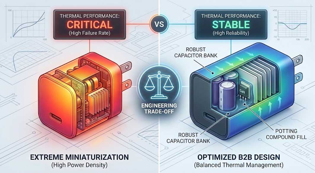
This is the most critical aspect often overlooked in specification sheets. There is a fundamental engineering trade-off between power density (W/in³) and thermal performance.
In the race to create the "world's smallest" type c wall charger, many designs compromise the isolation distance or reduce the size of the heatsink to dangerous levels. While a smaller footprint is marketable, physically smaller surface areas have less capacity to dissipate heat via convection.
From an engineering standpoint, a slightly larger casing is often superior for B2B applications where reliability is paramount. A charger that is 10% larger can accommodate a robust capacitor bank and a proper potting compound fill. Potting not only aids in Thermal Management by distributing heat evenly from the GaN FETs to the casing but also provides structural rigidity against drops. Therefore, sourcing managers should be wary of designs that prioritize extreme miniaturization over thermal stability, as the long-term failure rates for "ultra-compact" units are statistically higher due to component heat stress.
Design Philosophy for High-Reliability Chargers
Achieving a balance between performance and longevity requires a disciplined approach to circuit design, specifically regarding component derating and layout optimization.
For instance, in a specific engineering cycle for a 100W charging station, Tommox engineering teams opted to utilize a PFC (Power Factor Correction) stage combined with an LLC resonant converter, rather than a simpler flyback topology. While this decision increased the component count and initial BOM cost, it resulted in a flatter efficiency curve across the entire load range and significantly reduced voltage stress on the secondary rectifiers.
Effective design also prioritizes Failure Mode Analysis (FMA) during the prototyping phase. This involves:
Capacitor Derating: Ensuring electrolytic capacitors operate well below their rated voltage and temperature limits to maximize lifespan.
Loop Stability: Tuning the feedback loop to ensure the charger responds quickly to load transients (e.g., a phone waking up) without oscillating.
Protection Redundancy: Implementing dual layers of Over-Voltage Protection (OVP) and Over-Temperature Protection (OTP)—one via the controller and one via discrete hardware.
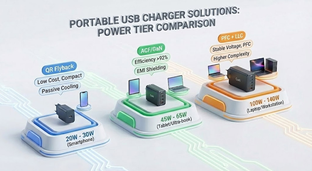
Specification Comparison: Portable USB Charger Solutions
When selecting a portable usb charger or a fixed wall unit, the architecture changes based on the power tier. Below is a comparison of typical design approaches for different power levels relevant to B2B procurement.
20W - 30W (Smartphone Focus):
Topology: QR Flyback.
Key Focus: Low cost, compact size.
Trade-off: Passive cooling is sufficient; efficiency is generally 85-88%.
Sourcing Tip: Ensure the type c wall charger supports PD 3.0 for wide compatibility.
45W - 65W (Tablet/Ultra-book Focus):
Topology: Active Clamp Flyback (ACF) or High-Frequency QR with GaN.
Key Focus: Efficiency (>92%) to manage heat in small enclosures.
Trade-off: Requires high-quality EMI shielding due to high-frequency switching.
Sourcing Tip: Look for [multi-port GaN charger solutions] that support dynamic power allocation.
100W - 140W (Laptop/Workstation Focus):
Topology: PFC + LLC Resonant Converter.
Key Focus: Stable voltage under heavy load, Power Factor Correction.
Trade-off: Higher cost and complexity; larger physical volume.
Sourcing Tip: Mandatory verification of PPS support for Samsung/latest flagship device compatibility.
FAQ for Procurement Managers
Q: Why is the "Ripple Voltage" specification important for a B2B buyer?
A: High ripple voltage causes excessive heat in the receiving device's battery management system (BMS). A quality type c wall charger should maintain ripple below 100mVp-p to ensure the longevity of the end-user's device.
Q: Does a heavier charger indicate better quality?
A: Generally, yes. In power electronics, weight often corresponds to better thermal potting (thermal glue) and more robust heat sinks. A strangely light charger may lack necessary thermal potting, leading to hotspots.
Q: What is the difference between PD 3.0 and PD 3.1?
A: PD 3.1 extends the power range up to 240W (48V/5A). For standard phone and laptop chargers (up to 100W), PD 3.0 remains the standard. If you are sourcing for high-performance gaming laptops, consider [high-power PD 3.1 adapters].
Q: How do I verify if a charger supports PPS?
A: PPS (Programmable Power Supply) allows for dynamic voltage and current negotiation. This must be explicitly stated in the protocol specification sheet. It is crucial for fast-charging Samsung devices and ensuring cool operation.
Future Trends in Charging Technology
The future of the type c wall charger lies in the integration of digital control and even higher power densities.
Digital Control Loops: Moving from analog to MCU-based digital control allows for smarter power distribution and real-time health monitoring of the charger components.
USB PD 3.1 & EPR (Extended Power Range): We will see the mainstream adoption of 140W and 240W chargers, blurring the line between proprietary laptop bricks and universal USB-C chargers.
Integrated Magnetics: innovative manufacturing techniques will allow transformers and inductors to be integrated into the PCB substrate, further reducing the Z-height of the portable usb charger.
For B2B buyers, staying ahead means prioritizing vendors who understand these engineering shifts and prioritize reliability over mere aesthetic miniaturization.
 What B2B Buyers Should Know Before Ordering Phone Chargers?