


Is a High-Power Charger Safe for Daily Use?
 06 Feb,2026
Introduction: The Engineering Logic Behind High-Power Safety
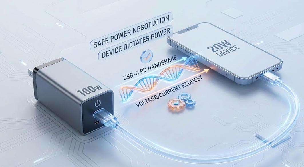
In the rapidly evolving landscape of consumer electronics, a common concern among procurement teams and end-users alike is whether a high-capacity power adapter is safe for low-power devices. The short answer is yes, but the engineering reality is more nuanced. When you connect a gan charger 100w to a smartphone that only requires 20W, safety is not determined by the charger's maximum capacity, but by the active communication protocols governing the connection.
Modern USB-C Power Delivery (PD) specifications rely on a rigorous "handshake" process. The charger acts as a passive provider until the device (the sink) requests a specific voltage and current profile. This article explores the internal architecture, thermal trade-offs, and critical failure mode analysis required to understand the safety and reliability of high-wattage power supplies.
Technical Fundamentals: Communication and Regulation
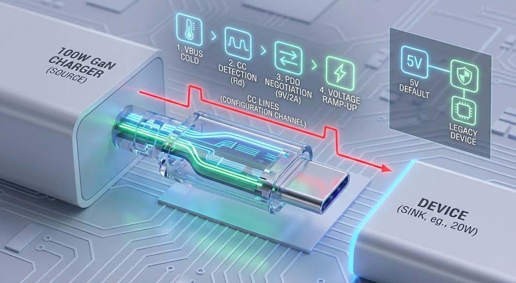
The safety of connecting a high-wattage source to a lower-wattage load is guaranteed by the architecture of the USB-C connector, specifically the Configuration Channel (CC) pins. A gan charger 100w does not "force" 100 watts into a device; rather, it advertises its capabilities (Source Capabilities) and waits.
The process follows a strict engineering sequence:
Vbus Cold: Initially, the charger provides no voltage (or a safe 5V) on the Vbus line.
Detection: The source detects the pulldown resistors (Rd) on the device via the CC lines.
Negotiation: The device selects a Power Data Object (PDO) that matches its battery management system (BMS) requirements (e.g., 9V/2A).
Contract Established: Only after this digital agreement does the charger ramp up voltage to the negotiated level.
If a gan charger 100w is connected to a legacy device without PD support, it defaults to the standard 5V rail, preventing over-voltage damage.
Engineering Trade-off Analysis: Density vs. Thermal Reliability
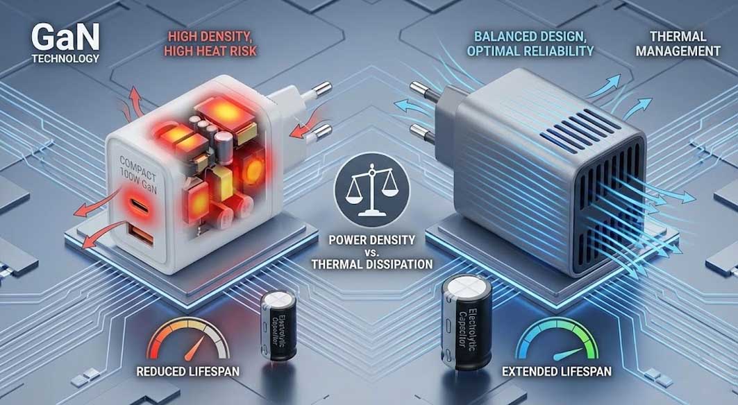
In the design phase of any high-performance power supply, there is an unavoidable conflict between power density (W/in³) and thermal dissipation. While marketing trends push for the smallest possible form factor, strictly engineering judgment suggests that extreme miniaturization often compromises long-term reliability.
When designing a gan charger 100w, reducing the PCBA footprint requires increasing the Switching Frequency Optimization. While Gallium Nitride (GaN) allows for faster switching with lower losses compared to silicon, higher frequencies concentrate heat in smaller magnetic components (transformers and inductors).
The Engineering Reality:
Thermal Saturation: Ultra-compact designs often reach thermal saturation faster. If the case temperature exceeds 75°C rapidly, the internal Over-Temperature Protection (OTP) will throttle power output, rendering the "100W" rating theoretical rather than continuous.
Capacitor Lifespan: Electrolytic capacitors are the primary limiting factor in charger longevity. Their lifespan halves for every 10°C rise in operating temperature. A slightly larger chassis allows for better airflow or potting compound distribution, significantly extending the Mean Time Between Failures (MTBF).
EMI Challenges: Higher density layouts increase the risk of Electromagnetic Interference (EMI) coupling, requiring aggressive filtering that can further impact efficiency.
Therefore, for B2B applications where reliability is paramount, selecting a charger with a balanced volumetric design is often superior to choosing the absolute smallest unit on the market.
Thermal Management in a 140W GaN Charger
As we scale up to a 140w gan charger utilizing the PD 3.1 standard (28V/5A), thermal management moves from passive cooling to active structural design. At this power level, standard flyback topologies are often replaced by PFC (Power Factor Correction) + LLC resonant converters to maximize efficiency.
Key thermal strategies include:
Potting Compound Injection: Fully encapsulating the PCBA in thermally conductive silicone or epoxy distributes heat away from hotspots (like the GaN FETs) to the outer casing.
High-Efficiency Topologies: utilizing Bridgeless Totem-Pole PFC stages can push efficiency above 95%, reducing the waste heat that needs to be dissipated in the first place.
Copper Shielding: Using copper sheets not only for EMI suppression but as heat spreaders to prevent localized overheating on the plastic enclosure.
Ripple Control in a 200W USB C Charger
A 200w usb c charger represents a multi-port distribution challenge. The primary engineering hurdle here is not just generating 200W, but maintaining low Voltage Ripple and Noise when multiple ports are loaded dynamically.
When a 200w usb c charger powers two laptops simultaneously, cross-regulation issues can occur. If Port A undergoes a sudden load transient (e.g., CPU spiking), it can induce voltage fluctuations on Port B. To mitigate this, distinct DC-DC buck converter stages are employed for each output port.
Critical Design Elements for Stability:
Independent Buck Circuits: Decoupling outputs ensures that a heavy load on one port does not degrade the signal quality on another.
Large Output Capacitance: High-quality solid capacitors are required to buffer the energy and smooth out the ripple, ensuring the sensitive Power Management IC (PMIC) of the connected laptop is not stressed.
Implementation Case Study: Thermal Thresholds
In a specific engineering validation sequence conducted at Tommox, the focus was placed on the correlation between potting compound density and junction temperature in high-power modules. The design team observed that while a partial potting approach reduced manufacturing weight, it created thermal air pockets that led to uneven heat distribution across the primary FETs during sustained 100% load testing. Consequently, the decision was made to implement a vacuum-potted assembly process. This choice increased the unit's physical weight by approximately 12 grams but resulted in a 6°C reduction in peak operating temperature, directly correlating to a projected 20% increase in component service life under industrial use conditions.
Comparison: 100W vs. 140W vs. 200W Applications
For OEM buyers, selecting the right tier involves understanding the use case rather than just the wattage number.
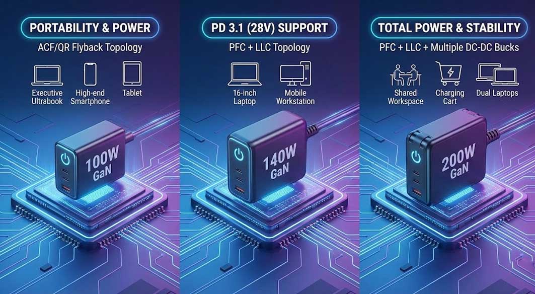
GaN Charger 100W:
Best For: Executive ultrabooks, high-end smartphones, and tablets.
Topology: Typically Active Clamp Flyback (ACF) or QR Flyback.
Sweet Spot: Balance of portability and power.
140W GaN Charger:
Best For: 16-inch Performance Laptops (MacBook Pro 16"), Mobile Workstations.
Topology: PFC + LLC.
Advantage: Supports PD 3.1 (28V output), essential for fast charging large batteries.
200W USB C Charger:
Best For: Shared workspaces, charging carts, dual-laptop setups.
Topology: High-power PFC + LLC + Multiple DC-DC Bucks.
Focus: Total power distribution and thermal stability over sustained periods.
To explore custom configurations for your specific regional requirements, consider reviewing our high-performance GaN charging solutions.
FAQ: Procurement & Technical Inquiries
Q: Can a 140W charger damage a device designed for 65W?
A: No. The Programmable Power Supply (PPS) and PD protocols ensure the charger only delivers what the device requests. The voltage is clamped at the negotiated level.
Q: Why do some chargers restart when a second device is plugged in?
A: This is a "power redistribution" reset. The controller must cut power momentarily to re-negotiate the PDOs and ensure the total output does not exceed the power supply's limit (e.g., splitting 100W into 60W + 40W).
Q: What is the significance of Ripple Noise in B2B selection?
A: High ripple can cause phantom touches on touchscreens and overheat device batteries. Engineering standards typically mandate ripple <150mVp-p under full load.
Future Trends: Digital Control and PD 3.1
The future of high-power charging lies in digital control loops. We are moving away from analog controllers to Digital Signal Processors (DSP) that allow for:
Real-time Efficiency Optimization: Adjusting switching frequency dynamically based on load.
Predictive Failure Analysis: Monitoring internal parameters to predict overheating before it happens.
Extended Power Range (EPR): Pushing voltages up to 48V (240W) requires updated safety capacitors and creepage distances on the PCB.
The gan charger 100w is becoming the new standard baseline, but the differentiation in the future will be defined by intelligence, thermal longevity, and adherence to rigorous Failure Mode Analysis standards.
 Everything You Need to Know About Modern Phone Chargers