


Single-Port vs Multi-Port Chargers: Pros and Cons Explained
 09 Feb,2026
The Evolution of Power Delivery Architectures
The landscape of power electronics has shifted dramatically over the last decade. We have moved from linear regulators and simple switching supplies to high-density architectures driven by the demand for consolidation. For B2B buyers and product managers, the choice between a dedicated single-port solution and a multi port usb charger is no longer just about user convenience; it is a complex calculation involving topology selection, thermal density, and component longevity.
As an engineer who has overseen the transition from Silicon to Gallium Nitride (GaN) in mass production, I have seen how the multi port usb charger has become the dominant form factor in consumer electronics. However, integrating multiple outputs into a compact chassis introduces significant engineering challenges regarding efficiency and cross-regulation. This article dissects these architectures to aid in informed procurement decisions.
Technical Fundamentals of Multi-Output Designs
To understand the reliability differences, we must look at the circuit topology. A single-port charger is a relatively linear chain: AC Input - EMI Filter - Rectification - Primary Switching (GaN) - Transformer - Secondary Rectification - Output. The output voltage is often regulated directly by the feedback loop of the main controller.
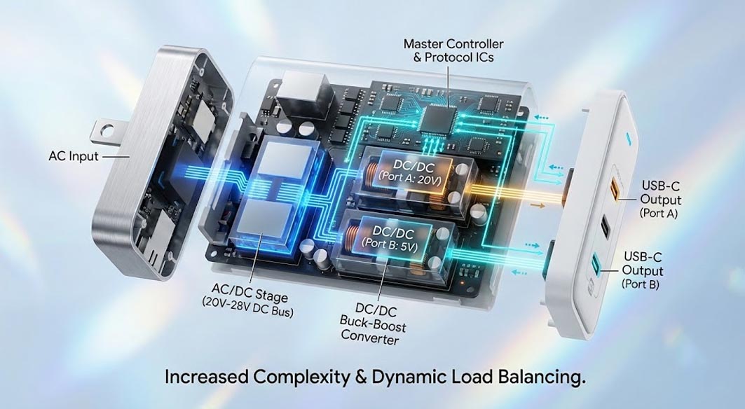
A multi port usb charger, however, introduces a secondary layer of complexity:
AC/DC Stage: Converts mains power to a fixed internal DC bus voltage (usually around 20V-28V for high-power PD applications).
DC/DC Buck-Boost Converters: Each port requires its own independent DC-DC stage. Since Port A might need 20V for a laptop and Port B might need 5V for headphones, the internal bus voltage must be stepped down (or up) individually for every port.
Protocol ICs: A master controller must manage the "handshake" (USB-PD communication) for every connected device and instruct the DC-DC converters on how much power to allocate.
This architecture enables Dynamic Load Balancing, but it also increases the component count by approximately 30-40% compared to a single-port equivalent, introducing more potential points of failure.
Engineering Trade-off Analysis: The Hidden Cost of Versatility
In power electronics, there is no such thing as a free lunch. When specifying a multi port usb charger for a product line, you are accepting specific engineering penalties in exchange for versatility.
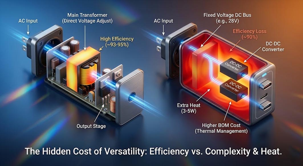
The primary trade-off is Efficiency vs. Complexity. In a single-port design, the main transformer can adjust its output to match the device's voltage request directly. In a multi-port design, the main transformer usually outputs a fixed high voltage, and secondary DC-DC converters regulate the final output. Every stage of conversion incurs power loss in the form of heat.
Single-Port: One conversion stage (High efficiency, ~93-95%).
Multi-Port: Two conversion stages (AC to DC Bus + DC to Output). Even if both stages are 95% efficient, the total system efficiency drops ($0.95 x 0.95 = 0.9025 or ~90%).
This 3-5% efficiency loss might seem negligible, but at 100W, that is 3-5 watts of extra heat trapped inside a small plastic enclosure. This necessitates more aggressive Thermal Management strategies, such as potting compounds or copper heat spreaders, which drive up the BOM (Bill of Materials) cost. For strictly industrial applications where reliability is paramount and device types are uniform, single-port topologies often remain the superior engineering choice.
Design Implementation and Thermal Logic
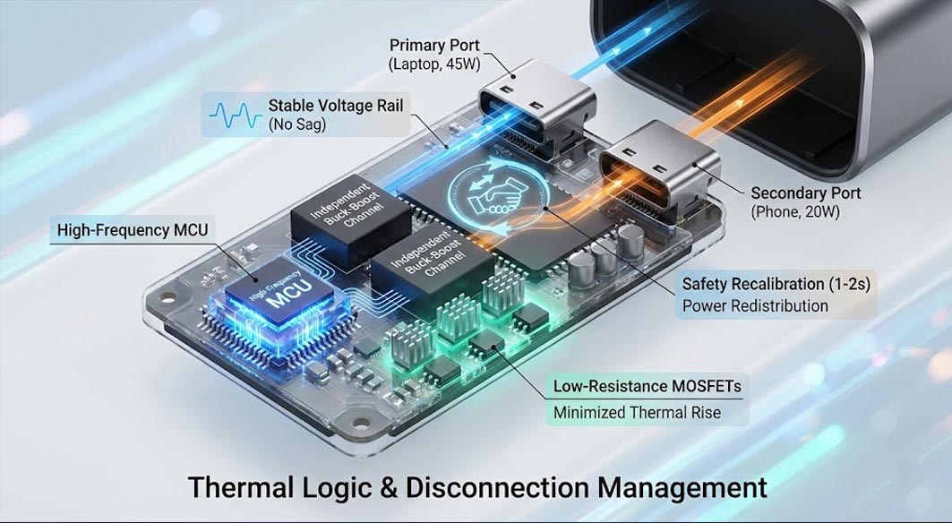
The challenge in modern charger design is managing the "disconnection event." When a user plugs a second device into a multi port usb charger, the system often cuts power to the first device for 1-2 seconds. This is not a defect; it is a safety recalibration. The controller must re-read the e-marker chips of the cables and redistribute the power budget (e.g., splitting 65W into 45W + 20W).
In a specific high-density reference design evaluated by Tommox engineering teams, the implementation of independent buck-boost channels was paired with a high-frequency MCU to minimize this handshake latency. By utilizing low-resistance MOSFETs in the secondary stage, the design minimized the thermal rise during the load-balancing phase. The engineering choice here focused on prioritizing the stability of the primary high-power rail (the laptop port) to ensure that even during reconfiguration, the voltage sag did not trigger a device reset. This approach illustrates the necessity of firmware optimization alongside hardware selection.
Industry Pain Points in Mass Production
When sourcing charging solutions, buyers often encounter specific failure modes associated with poorly designed multi-port units:
The "Reset" Phenomenon: As mentioned, cheap controllers take too long to renegotiate power, causing laptops to stop charging or external hard drives to disconnect, leading to data loss.
Thermal Throttling: To pass safety certifications (UL/CE), chargers have thermal cutoffs. A poorly thermally optimized multi port usb charger will aggressively throttle power (e.g., dropping from 65W to 15W) after 30 minutes of full load, rendering it useless for fast charging.
Cross-Regulation Noise: Inadequate filtering can cause electrical noise from a high-power port (charging a laptop) to bleed into a low-power port (charging audio equipment), causing hum or interference.
Comparison: Single-Port vs. Multi-Port Specifications
For procurement decision-makers, comparing these two categories requires looking beyond just the total wattage.
Single-Port Chargers
Topology: LLC Resonant or Flyback (Simpler).
Efficiency: Highest (Direct regulation).
Reliability: High (Fewer components, lower thermal stress).
Best Use Case: Bundled in-box chargers for specific devices (Laptops, Drones), industrial fixed-voltage applications.
Cost: Lower cost per unit, but higher cost per device charged.
Multi-Port USB Charger
Topology: PFC + LLC + Multiple DC-DC Buck Converters.
Efficiency: Moderate (Double conversion losses).
Reliability: Moderate (Dependent on thermal design and firmware stability).
Best Use Case: Aftermarket accessories, travel adapters, shared office workspaces, multi-device charging stations.
Cost: Higher BOM cost, but replaces multiple distinct chargers.
FAQ: Engineering & Sourcing Perspectives
Q: Why do some 100W multi-port chargers only output 65W when two ports are used?
This is due to Power Sharing limitations. A 100W rating usually refers to the total capacity or the max of a single port. The internal transformer has a physical limit. If Port A draws 65W, only 35W remains for the rest of the system.
Q: Does GaN technology eliminate the heat issue in multi-port chargers?
No. GaNFast chips improve switching efficiency, allowing for smaller transformers and capacitors. However, the power density (Watts per cubic inch) increases drastically. While GaN generates less heat, the smaller surface area makes dissipating that heat harder.
Q: Can I use a consumer multi-port charger for an industrial fleet of tablets?
Proceed with caution. Consumer chargers are designed for intermittent use. Industrial applications often require 24/7 uptime. Look for B2B-grade units with higher MTBF (Mean Time Between Failures) ratings and better ripple control.
Future Trends: The Next Generation of Power
The future of the multi port usb charger lies in intelligent, real-time power allocation without interruption.
Solid-State Transformers: Emerging tech that may eventually replace wire-wound transformers, allowing for even thinner profiles.
Power Sharing 2.0: New protocols aim to eliminate the "reset" disconnect by reserving power buffers, allowing devices to remain connected while the budget is recalculated.
Hybrid Power Architectures: Combining AC-DC conversion with internal battery buffers to handle peak power demands without stressing the grid.
For distributors and OEMs, the shift is clear: the market demands density. However, ensuring that this density does not compromise the fundamental safety and longevity of the device remains the core engineering challenge.
 Fast Charger vs Standard Charger: What’s the Real Difference?